A voltage comparator chip is a chip that contains 1 or more op amps.
Voltage level detector meaning.
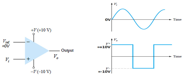
A comparator circuit compares two voltages and outputs either a 1 the voltage at the plus side or a 0 the voltage at the negative side to indicate which is larger.
Voltage level detector circuit simulation response.
Although operating cmos gates on the same 5 00 volt power supply voltage required by the ttl gates is no problem ttl output voltage levels will not be compatible with cmos input voltage requirements.
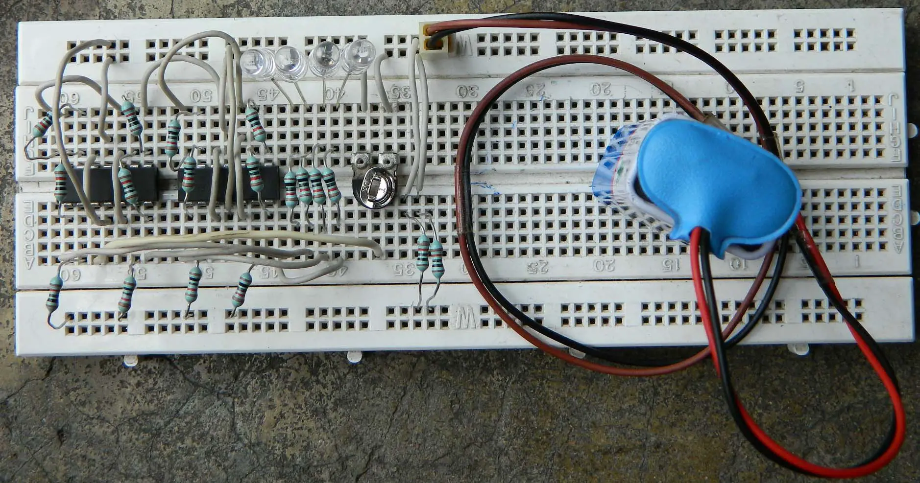
This is a really simple level voltage detector circuit.
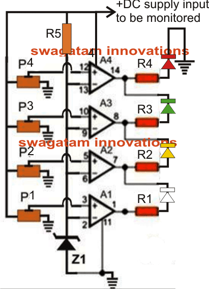
Now as the potentiometer is swiped across its range a count can be observed represented by the four led s.
In other words the op amp voltage comparator compares the magnitudes of two voltage inputs and determines which is the largest of the two.
Voltage level detectors operational amplifiers are often used in circuits in which the output is switched between the positive and negative saturation voltages v o sat and v o sat the actual voltage change that occurs is known as the output voltage swing for many op amps the output saturation voltages are typically the supply voltage levels minus 1 v.
An operational amplifier op amp has a well balanced difference input and a very high gain this parallels the characteristics of comparators and can be substituted in applications with low performance requirements.
What is a voltage sensor.
Voltage sensors can determine both the ac voltage or dc voltage level.
As shown in figure below we use the lm741 op amp circuit highly popular is the base of a circuit.
Usually this ac output voltage is converted by suitable electronic circuitry to high level dc voltage or current that is more convenient to use.
The lvdt s electrical output signal is the differential ac voltage between the two secondary windings which varies with the axial position of the core within the lvdt coil.
To see if the circuit is working or not use a potentiometer connect its two ends to the two poles of the battery connect the wiper to the first stage of the circuit.
Using a single op amp we can.
And we can build a voltage sensor circuit simply with a voltage comparator chip or an op amp that can function as a voltage comparator.
This is a voltage sensor circuit where if we get to a certain level of voltage then the output will turn on.
The input of this sensor can be the voltage whereas the output is the switches analog voltage signal a current signal an audible signal etc.
It can be a simple pen shaped piece of testing hardware that indicates the existence of electricity or an advanced tool that detects precise voltage levels in electrical systems.
A voltage sensor is a sensor is used to calculate and monitor the amount of voltage in an object.
I like it so much because it causes me to know the principle of the comparator circuit form.
The differing voltage level requirements of ttl and cmos technology present problems when the two types of gates are used in the same system.